The problem
A client was buying the Reduced Airflow IC Box, but discovered it did not meet the maximum airflow requirements of the Florida state code.
In this case this was the Florida Building Code, which prescribes 2 CFM max airflow at a negative pressure of 75 Pascals. Since then, similar airflow restrictions have been imposed in many jurisdictions.
Tripar’s technical specialists analyzed the problem. They saw that the integral junction box used on these IC boxes was already gasketed and had knockouts of the “press-back” type that also did not contain screwdriver slots, meaning that the leakage was elsewhere.
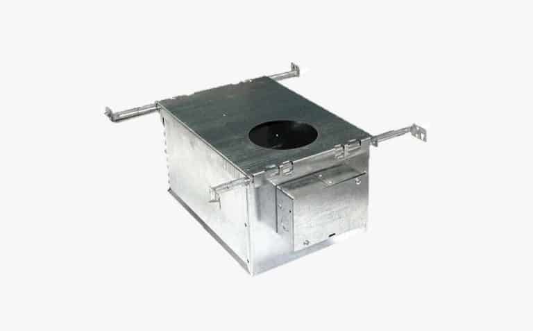
IC box assembly
The solution
Analysis showed excess airflow coming from two places:
- Joints within the box itself were overlapping, but there remained infinitesimal gaps over the length of the seams.
- The plaster frame was riveted to the IC Box both on the top and on two long edges, but the interface between the two was insufficient.
Tripar’s engineers attacked both sources of excess airflow by:
- Applying a caulking to all interior joints of the IC Box.
- Applying a gasket to the perimeter of the underside of the plaster frame where it contacted the riveted IC Box.
Samples were sent to the client which easily passed the prescribed airflow test.
The results
Tripar has successfully promoted and sold tens of thousands such IC Boxes and plaster frames to clients, coining the term “Ultra-Airtight”, indicating that they meet extremely stringent airflow requirements.
Tripar had airflow tests performed on the Ultra-Airtight I.C.Boxes by an independent and certified lab and passed with flying colors, obtaining airflow rates of under 0.2 cfm (10% of the 2 cfm permissible!)