Metal Fabrication vs Metal Stamping for Sheet Metal Components

Overview

When needing to produce a component out of sheet metal there are many options, but the two most commonly used manufacturing processes are metal stamping and CNC metal fabrication. Sometimes the decision between the two options is a clear-cut choice, other times it may be more difficult with arguments being made in favor of one manufacturing processes over the other. Below we will take a look at what is entailed in both metal fabrication and metal stamping processes. Additionally, we will provide some helpful advice for determining which manufacturing process is best suited for your needs.

Metal Stamping

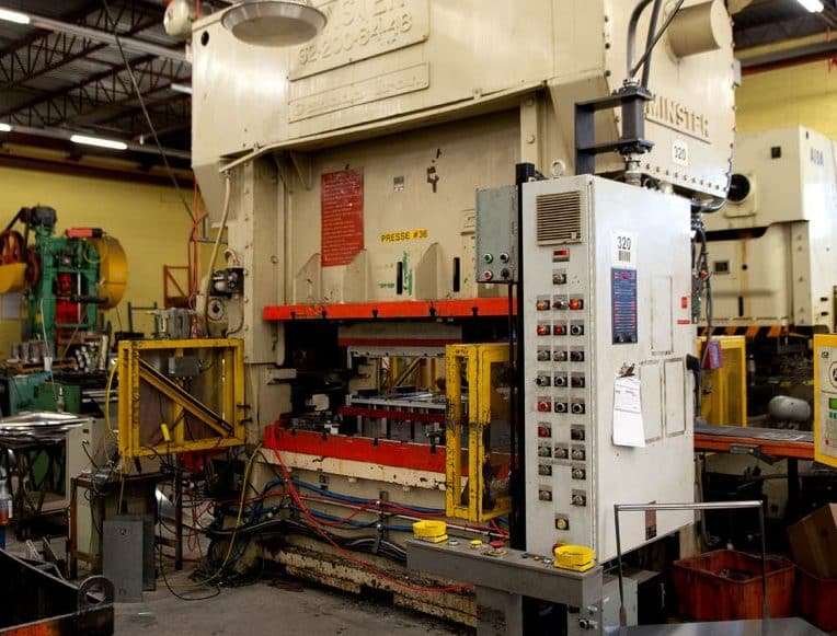
Metal stamping is most often used to transform flat sheet metal into the required 2D or 3D shapes. Metal stamping is typically done using mechanical or hydraulic presses of increasing tonnage, and one or more metal stamping dies are used to form many or all features of a sheet metal part. Some of the techniques used to achieve the desired results are blanking, punching, coining, bending, embossing, drawing, deep drawing, and more.

Metal Fabrication

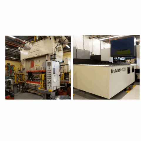
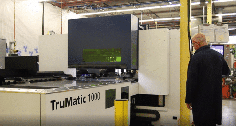
CNC (Computer Numerically Control) fabrication is a manufacturing process whereby computer software is pre-programmed to control the necessary machines movements and tools that are needed to create the desired end product. This process encompasses machinery including punch presses (often called a “Strippit”), CNC Punch Press, CNC Lasers, or CNC Punch/Laser Combination machines, followed by bending if/as required using CNC Press Brakes. Learn more about the capabilities of CNC machines.

Which Manufacturing Process Is Right for You?

Depending on the task at hand, it can be difficult to decide which manufacturing process would best suit your needs and deliver the results you expect. Below you will find a general overview of when CNC fabrication vs metal stamping are recommended for your sheet metal manufacturing needs, including their potential limitations.

Metal Fabrication

Best suited for:

  • Lower-mid range quantities
  • Short product lifecycle
  • Quicker to get the new part to market (days or a few weeks)*
  • Easier to adapt or change the design*

*Due to little to no tooling

Limitations:

  • Higher labour content so higher unit price
  • Slower production speed

Metal Stamping

Best suited for:

  • Items with mid-high production quantities
  • Obtaining the lowest possible unit part cost
  • Long product lifecycle
  • Better & more consistent quality and lower scrap rate

Limitations:

  • Tooling can be costly
  • Leadtime to design and produce dies means longer to get the new part to market (months)

Hybrid Manufacturing

Luckily, there is the potential to get the best of both worlds, and this is a term we have coined as Hybrid Manufacturing. This manufacturing process marries the benefits of both metal stamping and CNC fabrication, allowing them to support one another and improve overall production. With hybrid manufacturing, a component can be either fully or partially metal stamped for economies of scale, and then customized to pinpoint accuracy on CNC fabrication equipment. With this option, you are able to get a combination of the benefits from both manufacturing processes while reducing the limitations experienced by only using one. Learn more about the incredible benefits of hybrid manufacturing today.

Sheet Metal Design – What is a K-factor?

CNC bending metal parts

Introduction

One of the phenomena sheet metal fabricators must contend when bending parts is something called bending allowance. The reason for this is that when metal is bent, the material on the inside of the bend compresses, while the material on the outside stretches, and not by equal amounts (for reasons that get too technical even for this article). The result is that the workpiece actually “grows” in overall size if not compensated for. This compensation can be calculated using something called the K-factor, which considers variables such as the type of material, its thickness, the inside radius of the bend, and how it is bent.

What does this mean to the part designer? Even if your part is designed as a sheet metal part in a CAD Solids Modeler, when flattened, the flat development may or may not be correct, depending on the above-noted variables. It is for this reason that reputable metal fabricators may revise the model, and add their particular press brake bending parameters to create an updated flat development that will yield the part you require, and within your required tolerances.

Knowing your fabricator’s process and press brake tooling available (notably the radius of the male break dies), goes a long way to save time and potential surprises. The purpose of this article is to demonstrate to engineers and designers the technical aspects of how we (and you!) can determine the K-factor in sheet metal design.

Problem Statement

When files are provided by the customer, the 3D model has no bending parameters specified if it’s a STEP, IGES, or Parasolid file, and bending parameters are set to a default value in SolidWorks. When the flat pattern is developed for the part to be cut, it will often have incorrect dimensions to yield the customer’s desired bent part. In order to overcome this problem, your sheet metal fabricator should calculate the K-factor and revise the part’s flat development to yield your desired part within your specified tolerances.

Why is K-factor important in sheet metal manufacturing?

The K-factor in sheet metal design is important since it is used to correctly calculate flat patterns. This is because it is directly related to how much material is stretched during bending. K-factor is the ratio of the neutral axis to the material thickness. K-factor plays a key role in understanding the limits a material can handle during sheet metal bending.

General equation for K-factor:

BA= Bend Allowance

μ= Material Thickness

ρ = Inside Radius

β = Bend Angle (in degrees)

Calculating K-factor

1. Measurements taken from a bracket we manufacture:

β = 90°
ρ = 0.142 in (see Fig. 1)
μ = 0.135 in (Hot Rolled Steel)

FL1 = 1.378 in (see Fig. 2)
FL2 = 1.462 in (see Fig. 3)
Initial length = 2.583 in (see Fig. 5)

FIG. 1
Fig. 2
FIG. 3

2. Now that you have your measurements, we’ll determine the BA. To do this, first determine to bend outside set back (OSSB)

OSSB=Tan (β/2)(ρ+μ) Tan (90/2)(0.142+0.135)
OSSB = .277 in
FIG. 4
FIG. 5

Then determine the bend deduction (BD is not part of the formula but can be used instead of the K factor if desired).

BD = FL1 + FL2 – Initial length

3. Calculate bend allowance using the following equation

BA = 2*OSSB
= 2* 0.277
= 0.297 in

4. Plug the Bend allowance (BA), the Bend Angle (β), Inside Radius (ρ), and Material Thickness (μ) into the below equation to determine the K-factor (K).

Conclusion

A practical method to calculate the K-factor

1. PREPARE SAMPLES

- Begin by preparing 5 sample blanks which are of equal and known sizes .
- Record material type and thickness in test report
- The blanks should be at least a foot long to ensure an even bend, and a few inches deep to make sure you can sit them against the back stops.
- Measure Initial length of metal blank

2. BEND TESTING

- Set up the press brake with the desired tooling you’ll be using to fabricate this metal thickness. Make sure to use the same die and punch for all samples. If different punch or die is used it needs to be mentioned in the test report.
- Place a 90° bend in the center of the piece.

3. MEASURE SAMPLES

- Measure the flange length and inside radius of each piece, record length A,B and radius R as shown in the Fig. 6.
- The test report should have material type, material thickness, initial blank length, inside radius, flange length A and B at this step.

4. CALCULATION

- Calculate the K-factor by following the procedure mentioned earlier with the measurements obtained.
- This K-factor value is to be used in the trail-and-error approach in the following steps.

5. MODELLING

- Use the flange lengths measured to create a model on SolidWorks as shown in Fig. 7 and set the K-factor value obtained from the calculation (Step 4) in the SolidWorks model.

6. VERIFY

- Finally, develop a flat pattern from the model, and adjust the K-factor in SolidWorks until the flat pattern dimensions are equal to the measured initial length of the metal blank. The right K-factor of the metal that is being tested is when the overall flat pattern dimensions are equal to the measured initial length of the metal blank.

FIG. 6
FIG. 7

T-Grid Plate

Use our customizable T-Grid Plate with a pair of bar hangers! Integral bar hanger pockets on opposing sides accept our proven 1287 bar hangers.

Continue reading