Part II: Feature Design
As a metal fabricator, we see designs which are complex, but when analyzed, have few inherent features that are difficult to realize. The result is what all OEMs want; a design which meets their requirements for the lowest possible part cost, with consistent results from the fabricator. All too often, OEMs have not considered Design for Manufacturability (DFM), (or to the degree they should), only to see quotes that are far higher than they anticipated, or worse, no quotes due to inherent impossibilities.
Another reason for lack of DFM could be due to the Designer’s perception of how the part will be manufactured. It could be that since initial volumes may be on the lower end, the designer is thinking of the part being made by flexible manufacturing processes, such as CNC laser, punching and bending, designing the part as such. Exploiting the capabilities of these incredible machines is often a great starting point; to look at the capabilities please download our CNC Punch/Laser Design Guide.
However, as volumes increase, hard tooling may offer more economical solutions. If the Designer did not consider how the same part might be hard tooled, (made in one or more dies), it may prevent the part from being hard tooled, even as higher volumes might dictate, or not without design changes.
Whether the part will be made by flexible manufacturing processes such as CNC Laser, punch and bending, or hard tooled in progressive dies, the design principles remain the same. Based on our experience as both a metal stamper & fabricator, the following are many examples of do’s & don’ts to achieve DFM:
1. DON’T place holes/slots too close to one another. Minimum edge to edge distance between hole/slots is recommended to avoid metal distortion, deformation and fracturing. In the case of die stamping, if two adjacent holes/cut-outs are too close to one another, there will be insufficient strength in the bridge between the two for the tool steel to withstand the punching forces. There are ways around this, such as punching one hole in one station, then advancing the material to another station where the second is punched (with the holes still ending up adjacent to one another). Since the two holes within the die are now separated, there is sufficient tool steel around each hole. However, this is also achieved at a cost, since the die is now longer, and possibly a new station has been added that might otherwise not have been required if the separation between holes or features was greater.
As a rule of thumb, and as shown in figure 1, try to keep the distance between holes (the distance from closest edge to closest adjacent edge) at least 2 times the material thickness, and preferably 3 times.
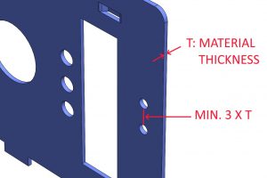
Figure 1: Minimum distances between holes or cut-outs.
2. DON’T place holes/slots too close to the bend edge. For example, whether a short upward bend needs to be next to a hole or cut-out, keeping a minimum distance between them will solve what could otherwise lead to distortion, deformation, fracturing and other problems. For example, with CNC punching, if an upward bend is too close to a punched hole, the upper die head in the CNC punch press could interfere with the bend, necessitating an extra operation at added cost.
As a rule of thumb, keep a minimum distance between the bend and the closest edge of the hole/slots 2 times material thickness plus the bend radius (dimension “S” below).
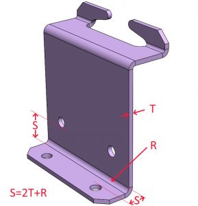
Figure 2: Minimum distance between holes and bends.
3. DON’T have bends too close to the edge of the material. Say for example, a .09” high bend is desired near the edge of a piece that is made from .06” thick sheet. As shown in figure 3, there is much more material being supported in the V-die on one side than the other.
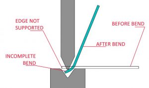
Figure 3: Imbalanced bending due to short leg.
This leads to unbalanced frictional forces, which often lead to either an incomplete bend, or a bow in the material. If a smaller V-die is used, so the same amount of die material is in contact with the sheet on both sides of the bend, the forces required to achieve the bend will rise, may still not prevent bowing, and may leave die marks on the outside of the bend due to the higher forces.
As a rule of thumb, and as shown in figure 4, try to have the shortest wall or leg in any bend at least equal to 3 times the material thickness plus the bend radius.
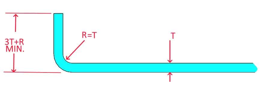
Figure 4: Minimum wall/leg height.
4. DON’T specify a tighter than necessary bending radius. As mentioned in DFM I, Tolerance Tolerant Designs, radii should be specified to the inside of bends or forms, as the outside is not as controllable, and is also affected by the material thickness tolerance. In addition, inside bend radii should ideally be equal to material thickness as shown in figure 4; less, in some cases will lead to various problems, including cracking on the outside of the bend and necking. Keeping the bend radius constant throughout the design can also increase the chances of allowing using same tool to be used through the bending process, potentially reducing set-ups, operations, and cost.
5. DO choose the minimum hole diameter that reduces punch loading and excessive burr. Keep in mind that small size punches are more prone to failure. Therefore the minimum hole diameter should never be less than the material thickness, and sometimes 2 times the material thickness for harder materials, as shown in figure 5. If for some reason the hole diameter must be less than the material thickness, it may be laser cut, but the required tolerance may not be achievable. For example, in the case of holes requiring a small PEM insert to be pressed in, the required hole tolerance is often +.003/-.000; something that may be not be achievable by laser cutting.
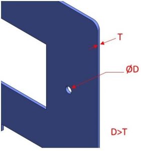
Figure 5: Minimum hole diameter.
6. Bend relief must be provided at the end of bent edges that meet, in order to avoid “overhangs” and tearing at bends. Overhangs become more prominent for thicker parts with smaller bend radii, and may even be as large as one half of the material thickness. Bends made too close to an edge may also cause tearing. As a rule of thumb, bend relief must be at least equal to the material thickness in width “W”, and be longer “L” than the bend radius, as shown in figure 6.

Figure 6: Bend relief before and after bending.
Conclusion
Remember that features and feature complexity correlate directly to part cost. Always try to simplify (or eliminate!) as many features as possible. If in doubt, ask your fabricator.
There are a great many ways in which to manufacture a part. Besides telling your fabricator the lot quantities you would like quoted, also try to give them your EAUs. They know their equipment, so they should be in a position to solve your problem for the lowest possible cost given the lot quantities and EAUs.
As noted in DFM I, if you are unsure, share your assembly with your fabricator. One who works in your interest, and understands and applies the techniques of DFM, may have cost-saving solutions for you.
For more information please contact TriparTech@TriparInc.com.
