Do you have a project in mind but not sure what tolerances to use? Don’t worry we got you covered. Here’s a overview that you can use to build your product.
In the absence of the client providing a drawing with agreed upon tolerances, the part(s) shall be manufactured as the per client’s supplied CAD model, with the following Tripar default manufacturing tolerances:

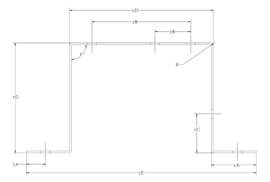
The sketch above is for illustrative purposes only.
Table 1. Default Tolerances
| DIM | Tolerance (“ ±) | Description |
|---|---|---|
| ±0.010” | Holes1 & linear dimensions of flat pieces < 0.5” | |
| ±0.015 | Holes1 & linear dimensions of flat pieces 0.5”< 4.0” | |
| ±0.020 | Holes1 & linear dimensions of flat pieces 4.0” < 12.0” | |
| Upon Review | Holes1 & linear dimensions of flat pieces > 12.0” | |
| A | ±0.010 | End to hole or bend |
| B | ±0.010 | Hole center-to-center (on one surface/plane) |
| C | ±0.015 | Bent edge to hole2 |
| D | ±0.020 | Distance over 2 bends2 |
| E | Undefined (TBD) | Distance over 3 or more bends2 |
| F | ± 2° | Angles3 |
| R | 1-2X Material thickness | Inside bend radii |
1 If the hole is not round, the above ranges apply to the largest dimension in the opening.
2 As measured nearest to bend(s).
3 Thin metals have some flexibility, and thus can deflect, even under their own weight. As such, tolerance applies up to 1” from the bend. For reference; 2° over 1” = .034”.
For those who provide, or are considering providing their own tolerance drawings, please see the following two TriparTech article on this subject, as well a sound sheet metal design practices;
Finish
Surface Finish: Shall be in accordance with material specified and associated governing specifications.
Formed or bent parts may have small surface blemishes near the areas of transition.
Residue: Metal fabricated parts are often produced and may be shipped with lubricants or dry film lubricants.
Protective Film: For raw materials which come with a protective film, parts shall be provided with this film, to help protect the parts until you, the customer remove when desired.
Burrs
Small burrs are an inherent part of metal stamping & fabrication processes. Being nearly impossible to quantify & measure, unless otherwise specified parts are provided in their “as stamped” or “as fabricated” condition.


