Introduction
There is far more than meets the eye when it comes to knockouts. This is especially so as they relate to luminaires, in which knockouts are governed by UL1598, Standard for Safety for Luminaires.
Knockouts can be with or without screwdriver slots, secured with one or more retention points (adjacent to one another, 180⁰ opposed, or some other angle apart), laser cut, or punched (through or pushed back). It is not always the designer’s choice which to use, as the application must be considered. This TriparTech attempts to make sense of it all!
Though UL1598 is the principal specification governing luminaires, additional institutional, municipal, and/or state laws can impose further requirements, thus there is unfortunately no absolute national standard.
A summary of these specs in relation to knockouts may be found in the Appendix A.
Knockout features
Screwdriver slot: Such slots* enable the desired knockout to be easily removed, simply by placing a screwdriver in the slot and prying it out. These must prescribe to the area limit contained in UL1598, para. 11.3.8
(see Appendix).
Retention point(s): Knockouts may contain a single point of retention (whose width is variable), or more than one. The width, number of retention points, and locations are a balance;
- A wider retention point will secure the knockout more but also leaves a larger burr upon being removed, (which may or may not interfere with conduit connectors).
- More than one retention point may permit each to be narrower (with less burr when the knockout is removed) but can often be more difficult to remove.
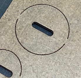
- If more than one, the retention points could be placed on opposing sides around the circumference (180⁰ apart), or closer to one another, the locations of which may require more or less force to remove. See the example of the image on the right, which contains two retention points spaced approximately 60⁰ apart.
Depending on the design, some will better resist the push-in, specifically the “Conduit knockout and twistout” spec of UL1598, para. 16.13 (see Appendix).
Knockout processes
Laser cut
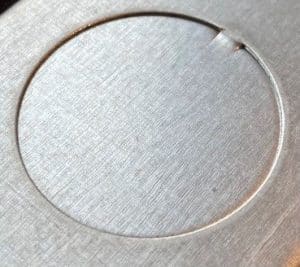
These typically contain a .010-.015” gap* (the minimum width of most lasers) cut around the circumference of the knockout, except at the point(s) of retention.
Punched (or stamped)
This is the most common process used to create knockouts, whether by metal stamping in a die, or done in a CNC punch press.
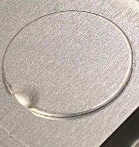
Because these are punched in (or out) from the base material with little to no clearance, there is no circumferential gap that is present on laser cut knockouts, but that is not to say that there will not be a gap of another kind. To pry or hit out such a knockout, the material must be fully sheared through. Depending on how much further the punch creating the knockout penetrates, there will be a gap between one surface of the base metal, and the opposite surface of the knockout. Just refer to your standard wall plug/switch, or octagonal box, or carefully look at the following photo; you will see a small gap* between .010-.015”.
Knockout direction or orientation
The direction or orientation of the knockout must also be considered. Generally, outwardly punched knockouts (with screwdriver slots) are preferred, because when properly punched/sheared from the base metal, these are very difficult to be pushed inward, invariably almost always passing the push-in test of UL1598, para. 16.13 (see Appendix).
The most common exception to this is for junction boxes that must remain airtight and/or are subject to airflow restrictions or must meet Chicago Plenum Act requirements. To keep gaps & airflow to a minimum, neither laser cut knockouts or screwdriver slots are used. As such, it is almost impossible to remove a knockout that has been pushed outward where access to hit it from the inside is limited, (e.g., from within a junction box). In such instances, knockouts are often pushed inward, but then restruck to partially push the knockout back from where it was sheared (often called “pushback” type knockouts). The result is a knockout with no gap, but one that can still be removed with a typical blow from a hammer and punch.
*These gaps/slots will be a source of airflow, which may or may not be a problem. Additionally, these same gaps/slots would violate the Construction Requirements for the City of Chicago Environmental Air Spaces (CCEA), commonly known as the Chicago Plenum Act. See Appendix for further details.
If you have a question or find any omissions or errors here, please let us know, but remember that your testing lab and UL are the final authority on this!
Appendix
UL1598 – Extracts relating to knockouts
Definitions:
Knockout – a partial cut-out opening that is closed until the precut material is removed.
Opening – an aperture in an enclosure that is covered or filled by a plug or knockout and that has the potential of becoming an open hole.
Specifications:
11.3 Junction boxes
11.3.8 An open hole in a box, such as a mounting-screw hole, shall have no dimension larger than 6.7 mm (0.265 in), except that a pryout hole or slot may be provided in a knockout for 1 in or smaller trade size conduit, provided that the area of the hole or slot is no more than 26 mm2 (0.040 in2).
16.13 Conduit knockout and twistout
16.13.1 The following test shall apply only to conduit entries and shall be performed on a sample securely held in place using the test apparatus described in Clause 19.23.
16.13.2 A force of 44 N (10 lb) shall be applied to a knockout for 1 min by means of a 6.4 mm (0.250 in) diameter mandrel with a flat end. The force shall be applied to the exterior surface of the knockout, in a direction perpendicular to the plane of the knockout, and at the point most likely to result in movement.
16.13.3 The knockout shall remain in place, and the clearance between the knockout and the opening shall be no more than 1.6 mm (0.063 in) when measured after the force has been removed.
Additionally, there are two more specs that may or may not be relevant;
Airflow:
When there is insulation in the ceiling, and municipal or state laws impose heat retention or specific airflow restrictions, (e.g. < 2 cfm under pressure (vacuum) of 1.57lbs/ft², ref. Florida Building Code Chapter 13 “Florida Energy Efficiency for Building Construction”, section 13-606.1.ABC.1.2.4 Recessed lighting fixtures), the luminaire must be enclosed by a metal barrier or enclosure (IC Box) that restricts airflow to the applicable specification(s). Some other states have similar specs.
It is noteworthy to mention that Tripar’s Ultra-Airtight IC Boxes (gasketed IC Box containing a gasketed junction box with all knockout holes of the “pushed back” type), when used in conjunction with gasketed plaster frames, have been tested to show less than 0.2 cfm airflow; see the I.C. Box Air Leakage. Though this is 1/10th of the 2 cfm maximum airflow imposed by various municipal and state regulations, it is important to note that any holes introduced will increase airflow, for which the OEM must test.
Chicago Plenum:
The Construction Requirements for the City of Chicago Environmental Air Spaces (CCEA), often referred to as the “Chicago Plenum Act”, imposes requirements that the IC Box must not have, amongst other requirements, any open holes. Though this spec does not contain any specific airflow metric, the mechanical aspects of this specification in part, require;
- Luminaire & wiring compartments to be sealed off and gasketed or otherwise have no openings.
- Unused screw openings shall be closed by use of metallic screws, rivets, sealant or equivalent.
- Junction boxes and covers shall have no holes, and all covers that open into the ceiling space shall be gasketed.
- All knockouts shall be of the “flush” or “press back” type.
For complete requirements, consult the specification; Section 18-27-300.22(c) of the city of Chicago Electrical Code. Once the complete assembly has been tested & listed to the applicable specification, the Recessed Luminaire is eligible for the marking, “CCEA” (City of Chicago Environmental Air other than Ducts and Plenums).