Tripar Default Manufacturing Tolerances

Do you have a project in mind but not sure what tolerances to use? Don’t worry we got you covered. Here’s a overview that you can use to build your product.

In the absence of the client providing a drawing with agreed upon tolerances, the part(s) shall be manufactured as the per clients supplied CAD model, with the following Tripar default manufacturing tolerances:

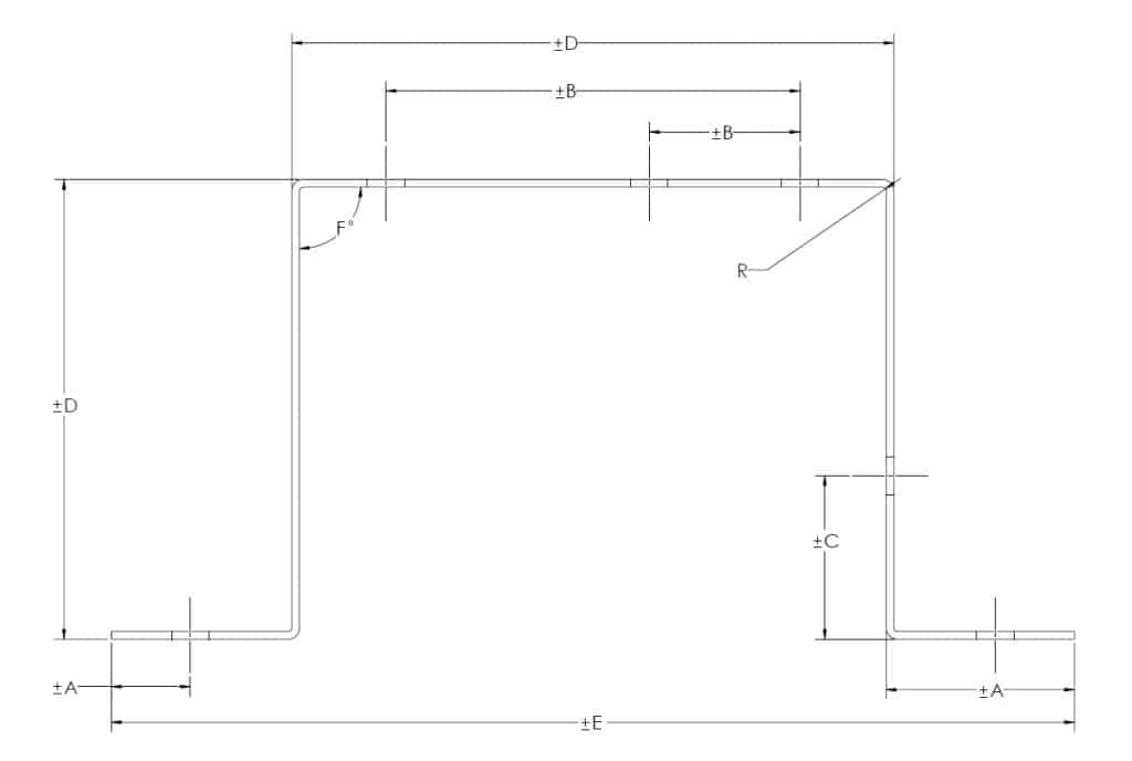
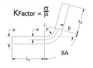
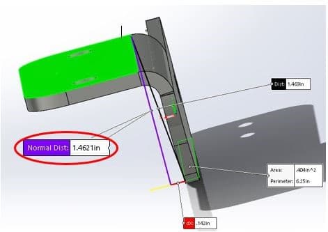
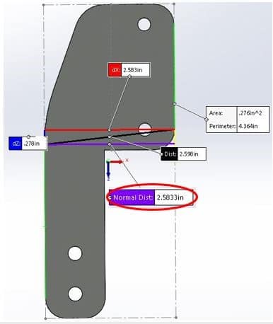
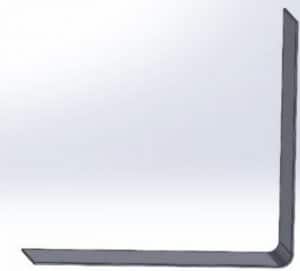
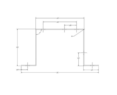
The sketch above is for illustrative purposes only. 

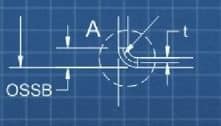
Table 1. Default Tolerances

DIMTolerance (“ ±)Description
±0.010”Holes1 & linear dimensions of flat pieces < 0.5”
±0.015Holes1 & linear dimensions of flat pieces 0.5”< 4.0”
±0.020Holes1 & linear dimensions of flat pieces 4.0” < 12.0”
Upon ReviewHoles1 & linear dimensions of flat pieces > 12.0”
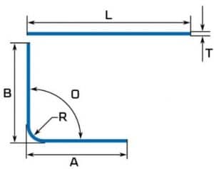
A±0.010End to hole or bend
B±0.010Hole center-to-center (on one surface/plane)
C±0.015Bent edge to hole2
D±0.020Distance over 2 bends2
EUndefined (TBD)Distance over 3 or more bends2
F± 2° Angles3
R1-2X Material thickness Inside bend radii

1 If the hole is not round, the above ranges apply to the largest dimension in the opening.

2 As measured nearest to bend(s). 

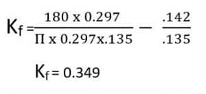
3 Thin metals have some flexibility, and thus can deflect, even under their own weight. As such, tolerance applies up to 1” from the bend. For reference; 2° over 1” = .034”. 

For those who provide, or are considering providing their own tolerance drawings, please see the following two TriparTech article on this subject, as well a sound sheet metal design practices; 

Finish

Surface Finish:  Shall be in accordance with material specified and associated governing specifications. 

Formed or bent parts may have small surface blemishes near the areas of transition. 

Residue: Metal fabricated parts are often produced and may be shipped with lubricants or dry film lubricants. 

Protective Film: For raw materials which come with a protective film, parts shall be provided with this film, to help protect the parts until you, the customer remove when desired.

Burrs

Small burrs are an inherent part of metal stamping & fabrication processes. Being nearly impossible to quantify & measure, unless otherwise specified parts are provided in their “as stamped” or “as fabricated” condition. 

Sheet Metal Design – What is a K-factor?

CNC bending metal parts

Introduction

One of the phenomena sheet metal fabricators must contend when bending parts is something called bending allowance. The reason for this is that when metal is bent, the material on the inside of the bend compresses, while the material on the outside stretches, and not by equal amounts (for reasons that get too technical even for this article). The result is that the workpiece actually “grows” in overall size if not compensated for. This compensation can be calculated using something called the K-factor, which considers variables such as the type of material, its thickness, the inside radius of the bend, and how it is bent.

What does this mean to the part designer? Even if your part is designed as a sheet metal part in a CAD Solids Modeler, when flattened, the flat development may or may not be correct, depending on the above-noted variables. It is for this reason that reputable metal fabricators may revise the model, and add their particular press brake bending parameters to create an updated flat development that will yield the part you require, and within your required tolerances.

Knowing your fabricator’s process and press brake tooling available (notably the radius of the male break dies), goes a long way to save time and potential surprises. The purpose of this article is to demonstrate to engineers and designers the technical aspects of how we (and you!) can determine the K-factor in sheet metal design.

Problem Statement

When files are provided by the customer, the 3D model has no bending parameters specified if it’s a STEP, IGES, or Parasolid file, and bending parameters are set to a default value in SolidWorks. When the flat pattern is developed for the part to be cut, it will often have incorrect dimensions to yield the customer’s desired bent part. In order to overcome this problem, your sheet metal fabricator should calculate the K-factor and revise the part’s flat development to yield your desired part within your specified tolerances.

Why is K-factor important in sheet metal manufacturing?

The K-factor in sheet metal design is important since it is used to correctly calculate flat patterns. This is because it is directly related to how much material is stretched during bending. K-factor is the ratio of the neutral axis to the material thickness. K-factor plays a key role in understanding the limits a material can handle during sheet metal bending.

General equation for K-factor:

BA= Bend Allowance

μ= Material Thickness

ρ = Inside Radius

β = Bend Angle (in degrees)

Calculating K-factor

1. Measurements taken from a bracket we manufacture:

β = 90°
ρ = 0.142 in (see Fig. 1)
μ = 0.135 in (Hot Rolled Steel)

FL1 = 1.378 in (see Fig. 2)
FL2 = 1.462 in (see Fig. 3)
Initial length = 2.583 in (see Fig. 5)

FIG. 1
Fig. 2
FIG. 3

2. Now that you have your measurements, we’ll determine the BA. To do this, first determine to bend outside set back (OSSB)

OSSB=Tan (β/2)(ρ+μ) Tan (90/2)(0.142+0.135)
OSSB = .277 in
FIG. 4
FIG. 5

Then determine the bend deduction (BD is not part of the formula but can be used instead of the K factor if desired).

BD = FL1 + FL2 – Initial length

3. Calculate bend allowance using the following equation

BA = 2*OSSB
= 2* 0.277
= 0.297 in

4. Plug the Bend allowance (BA), the Bend Angle (β), Inside Radius (ρ), and Material Thickness (μ) into the below equation to determine the K-factor (K).

Conclusion

A practical method to calculate the K-factor

1. PREPARE SAMPLES

- Begin by preparing 5 sample blanks which are of equal and known sizes .
- Record material type and thickness in test report
- The blanks should be at least a foot long to ensure an even bend, and a few inches deep to make sure you can sit them against the back stops.
- Measure Initial length of metal blank

2. BEND TESTING

- Set up the press brake with the desired tooling you’ll be using to fabricate this metal thickness. Make sure to use the same die and punch for all samples. If different punch or die is used it needs to be mentioned in the test report.
- Place a 90° bend in the center of the piece.

3. MEASURE SAMPLES

- Measure the flange length and inside radius of each piece, record length A,B and radius R as shown in the Fig. 6.
- The test report should have material type, material thickness, initial blank length, inside radius, flange length A and B at this step.

4. CALCULATION

- Calculate the K-factor by following the procedure mentioned earlier with the measurements obtained.
- This K-factor value is to be used in the trail-and-error approach in the following steps.

5. MODELLING

- Use the flange lengths measured to create a model on SolidWorks as shown in Fig. 7 and set the K-factor value obtained from the calculation (Step 4) in the SolidWorks model.

6. VERIFY

- Finally, develop a flat pattern from the model, and adjust the K-factor in SolidWorks until the flat pattern dimensions are equal to the measured initial length of the metal blank. The right K-factor of the metal that is being tested is when the overall flat pattern dimensions are equal to the measured initial length of the metal blank.

FIG. 6
FIG. 7